 |
AeroHydro,
Inc.
Relational 3D Modeling for Marine & Industrial Design
|
| Marine
design MultiSurf Gallery Users Hydro Flattener Suite AHVPP Industrial design
|
Paul Bogataj On the eve of the America's Cup we are very pleased to introduce an innovative
designer/engineer who has participated on leading design teams for the last three races. On the eve of the America's Cup we are very pleased to introduce an innovative
designer/engineer who has participated on leading design teams for the last three races.Paul
Bogataj has designed keels and rudders for the America’s Cup, performing research for
PACT in 1992, and designing the appendages for Team Dennis Conner in 1995 and Young
America in 2000, as well as various one-design sailboats. He is currently working on the
keel and rudder for an Open 60 for the upcoming Vendee Globe Challenge, and optimizing a
keel and rudder for an ILC Maxi. He is an aeronautical engineer by training with 11 years
experience at Boeing, but has made a focus out of applying advanced aerodynamic methods to
improve sailboat design. As an aeronautical engineer, he uses MultiSurf in a unique
application. Aside from lofting surface geometry with it, he also creates surface paneling
for input into computational fluid dynamic programs. The various curve and surface
construction methods within MultiSurf allow him to generate the needed shapes, and the
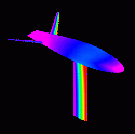
parametric nature of the surfaces lends itself to generating surface paneling. The example rendering (click on thumbnails for full-size images) is an America’s
Cup keel, bulb, and winglets and illustrates the various surfaces that were created using
MultiSurf. The photograph shows this same model mounted in a wind tunnel. The parts were
machined directly from IGES lofts produced using MultiSurf and provided to the builder.
The ability to loft designs and provide accurate information so they can be built
precisely is valuable to insure that what is being tested is what Because testing is expensive and takes a lot of time, from model construction until data is actually obtained, computational fluid dynamic (CFD) methods are used to model the flow around candidate designs in order to make progress more quickly. The value of testing is maximized by developing highly refined parts of competing ideas, thus yielding answers to well posed questions between equally mature designs of those concepts. The information provided by CFD solutions enhances the ability to improve the designs.
The computational method requires that the panels match exactly at the intersection of two parts, (keel to bulb, and bulb to winglets). By using the same intersection curve to define the final wireframes of two parts, the necessary abutment of points along that edge is achieved. The relational aspect of MultiSurf is very useful because the matching of points along their intersection is maintained when the shape of one or both of the parts is changed. The number of panels for input to the CFD code is controlled by the divisions settings
on each surface. Distribution of panels is adjusted by modifying the parameter space along
each edge using relabels. The result is proper and reproducible surface paneling suitable
for input into the CFD code with the panel corner locations output in the .PAT file. The colored image displays the results of the CFD flow solution from PANAIR, a second-order, potential flow method developed by Boeing under NASA contract. Each color represents a specific pressure and indicates details of the flow around the configuration. The CFD code computes the pressure due to the local flow velocity on every panel of the configuration. These can be displayed, as shown, to highlight the flow features, and are also integrated over the entire configuration to determine the forces and moments acting on the configuration by the fluid. Through these results, the performance of potential designs can be compared and the factors that influence their performance can be understood, allowing further improvement. Once a model has been appropriately created in MultiSurf, design iterations are easily made and the new surface paneling is automatically updated, due to the power of relational geometry. The new paneling is instantly ready for computational analysis to determine the effect of the changes. In this way many options are quickly explored leading to an optimized result. By using CFD methods to examine the performance of potential designs, it is possible to refine designs to levels not achievable otherwise. This is enabled by the ability to modify the designs and produce the paneling efficiently in MultiSurf. The completed design is then readily available as IGES output for accurate manufacturing. John Letcher says: "Paul is demonstrating some of the most profound potential of
MultiSurf and relational geometry: the ability to generate systematic variations of
geometric models for analysis, evaluation, and optimization. This concept could be applied
to hundreds of other design domains, wherever quantitative analysis methods have become
available." Paul Bogataj, Aeronautical Designer |


